
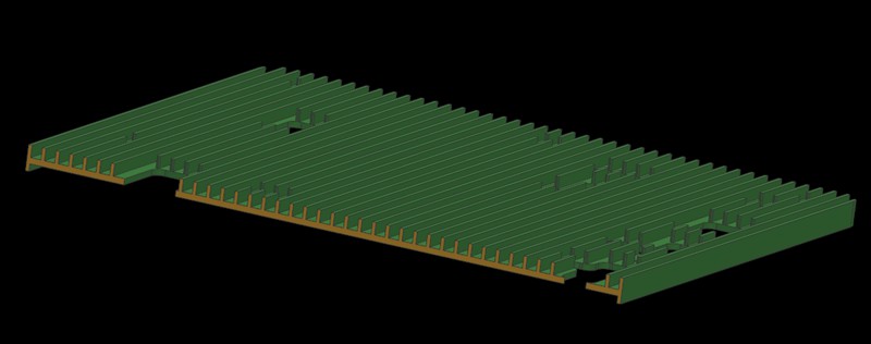
The case is about a shell part made of AL6061-T6 material. Here are its exact dimensions.
Overall Dimension: 455*261.5*12.5mm
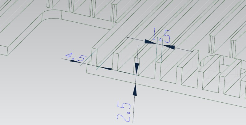
Support Wall Thickness: 2.5mm
Heat Sink Thickness: 1.5mm
Heat Sink Spacing: 4.5mm
During CNC vowin.cn/en/News/news1251.html' target='_blank'>machining, these thin-walled shell structures often cause a range of problems, such as warping and deformation. To overcome these issues, we try to offer serval process route options. However, there are still some exact issues for each process. Here are the details.
In process 1, we start by machining the reverse side (inner side) of the workpiece and then use plaster to fill in the hollowed-out areas. Next, letting the reverse side be a reference, we use glue and double-sided tape to fix the reference side in place in order to machine the front side.
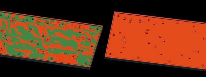
However, there are some problems with this method. Due to the large hollowing backfilled area on the reverse side, the glue and double-sided tape are not sufficiently secure the workpiece. It leads to warping in the middle of the workpiece and more material removal in the process (called overcutting). In addition, the lack of stability of the workpiece also leads to low processing efficiency and poor surface knife pattern.
In process 2, we change the order of machining. We start with the underside (the side where the heat is dissipated) and then use the plaster backfilling of the hollow area. Next, letting the front side as a reference, we use glue and double-sided tape to fix the reference side so that we could work the reverse side.
However, the problem with this process is similar to process route 1, except that the issue is shifted to the reverse side (inner side). Again, when the reverse side has a large hollowing backfill area, the use of glue and double-sided tape do not provide high stability to the workpiece, resulting in warping.
In process 3, we consider using the machining sequence of process 1 or process 2. Then in the second fastening process, use a press plate to hold the workpiece by pressing down on the perimeter.
However, due to the large product area, the platen is only able to cover the perimeter area and could not fully fix the central area of the workpiece.
On the one hand, this results in the center area of the workpiece still appearing from warping and deformation, which in turn leads to overcutting in the center area of the product. On the other hand, this machining method will make the thin-walled CNC shell parts too weak.
In process 4, we machine the reverse side (inner side) first and then use a vacuum chuck to attach the machined reverse plane in order to work the front side.
However, in the case of the thin-walled shell part, there are concave and convex structures on the reverse side of the workpiece that we need to avoid when using vacuum suction. But this will create a new problem, the avoided areas lose their suction power, especially in the four corner areas on the circumference of the largest profile.
As these non-absorbed areas correspond to the front side (the machined surface at this point), the cutting tool bounce could occur, resulting in a vibrating tool pattern. Therefore, this method can have a negative impact on the quality of the machining and the surface finish.
In order to solve the above problems, we propose the following optimized process and fixture solutions.
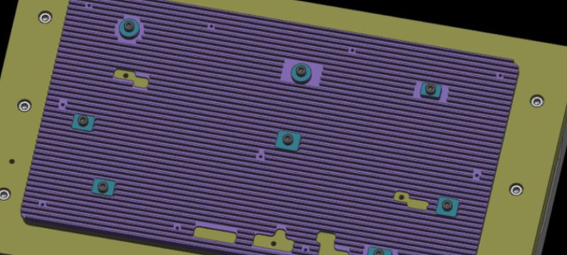
Firstly, we improved the process route. With the new solution, we process the reverse side (inner side) first and pre-machine the screw through-hole in some areas that will eventually be hollowed out. The purpose of this is to provide a better fixing and positioning method in the subsequent machining steps.
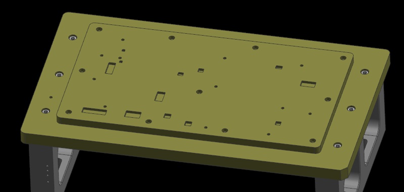
Next, we use the machined planes on the reverse side (inner side) as a machining reference. At the same time, we secure the workpiece by passing the screw through the over-hole from the previous process and locking it to the fixture plate. Then circle the area where the screw is locked as the area to be machined.
During the machining process, we first process the areas other than the area to be machined. Once these areas have been machined, we place the platen on the machined area (the platen needs to be covered with glue to prevent crushing of the machined surface). We then remove the screws used in step 2 and continue machining the areas to be machined until the entire product is finished.
With this optimized process and fixture solution, we can hold the thin-walled CNC shell part better and avoid problems such as warping, distortion, and overcutting. The mounted screws allow the fixture plate to be tightly attached to the workpiece, providing reliable positioning and support. In addition, the use of a press plate to apply pressure on the machined area helps to keep the workpiece stable.