
Is that part you just machined within tolerance? It’s either a yes or no answer in the world of manufacturing. Machining precision requires the consideration of some complex variables, including the size of your features, what tools you have, and the capabilities of your machine. All of these variables come together with the help of toolpaths to successfully produce parts within tolerance. In this article we’ll be focusing on how to plan your first 2D vowin.cn/en/News/news1251.html' target='_blank'>machining project with 10 CNC vowin.cn/en/News/news1251.html' target='_blank'>milling toolpaths.
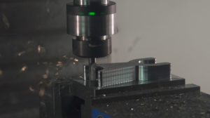
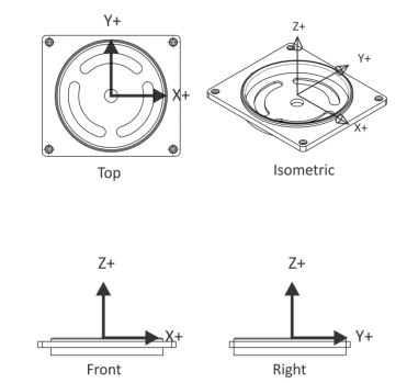
CNC milling toolpaths are typically categorized 2D, 3D, 4-axis, and 5-axis. However, the term 2D is a bit misleading since this toolpath uses the Z-axis to position a tool for depth. For example, in the image below we have a prismatic part whose features all reside at various heights on the XY plane. We can quickly position our tool to depth on the Z axis, and then machine a feature by moving in X and Y.
Many new CNC machinists struggle to plan out their toolpaths, especially as features get more complex. Sometimes this problem solving process is clear. Pockets use a 2D Pocket operation, chamfers use Chamfer Milling, and so on.
But then you get to the difficult questions that don’t have such black and white answers. How are you going to machine the hole in the center of the part above? You could use a drill, contour, or circular pocket toolpath. And which of these features needs to be machined from the top versus the bottom? The answer to these questions requires some fundamental toolpath knowledge.
Every toolpath has a unique behavior and use case. Familiarize yourself with the toolpaths below, which you’ll encounter in Fusion 360 and other CAM solutions.
| Toolpath | Uses |
| Face | Finishing the face of a part. |
| Contour | Machining loops, open pockets, stick fonts, dovetails, keysets, or saw cuts. |
| Chamfer | Deburring and creating chamfers using either a tapered mill or center drill. |
| Fillet | Creating fillets using a Corner Rounding Tool. |
| Roughing or finishing pockets of various shapes and sizes. | |
| Slot Mill | Machining straight slots or arc slots. |
| Drill | Creating spot drill, tapped, bore, or reamed holes. |
| Bore | Making holes, typically greater than .75in diameter. |
| Thread Mill | Machining ID threads over .75in diameter, milled OD threads of any size, or custom threads. |
There is also some toolpath lingo that you’ll want to get acquainted with. You’ll find the terms below referenced in nearly every CAM software package.
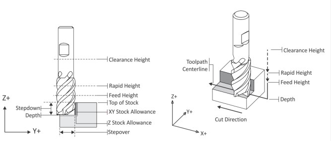
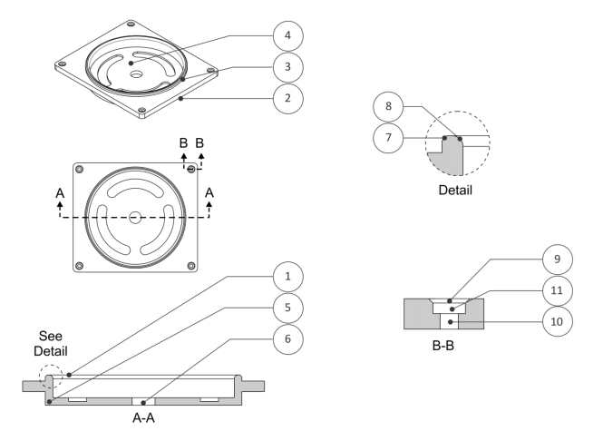
All of these terms and toolpath types come together in the planning of a 2D machining process. Check out the example below for how we might plan out the machining of a simple prismatic part.
| Step | Toolpath | Comments |
| 1 | Face | Roughs and finishes to the highest flat surface of part. |
| 2 | 2D Contour | Machines the outside of the part. |
| 3 | 2D Contour | Machines outside of circular boss. |
| 4 | 2D Pocket | Roughs and then finishes the circular pocket. |
| 5 | Slot Mill | Mills the arc slots. |
| 6 | Circular Pocket Mill | Machines the center through holes. Depending on size, a drill could also work here. |
| 7 | Chamfer | Uses a 2D contour and chamfer mill to create 45° angle. |
| 8 | Fillet | Uses 2D contour and corner round tool to make fillet. |
| 9 | Spot Drill | Pre-drills holes to prevent drill drift and to make a chamfer. |
| 10 | Drill | Machines holes. |
| 11 | Circular Pocket Mill | Machines counterbore. |
CDC adjusts a toolpath to account for tool wear that can cause inaccuracies in a part. This will basically align your tool either slightly to the left or right of the originally programmed toolpath. You can find your compensation value by subtracting actual dimensions from desired dimensions of a part feature.
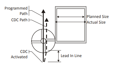
We always recommend activating CDC while the tool is away from the part. This will allow the angled movement of CDC to kick in fully before making contact with your material. Correctly implementing CDC to accurately machine 2D features is an important part of a successful machining practice. Check with your machine control and CAM software to make sure you understand how to enter the compensation value.
The plan that was just laid out uses 10 different milling toolpaths. Knowing how to use each one and understanding their limitations is the key to machining success. In the sections below we’ll be covering each toolpath in detail along with some guidelines to consider.
You’ll use facing at the start of your machining process to remove any excess material down to the topmost flat face of a part. We recommend using a Face Mill for most parts. This will provide the highest rates of material removal.
You’ll want to start your toolpath with just enough distance from the part so the face mill doesn’t plunge into the stock material. The distance from the center of the tool should be the tool radius plus some clearance.
We also recommend planning your roughing passes based on stock material cuts that can vary in thickness by up to .05 inches. Basically, plan for the worst case material size with maximum height and additional roughing passes. This will ensure that your tool doesn’t meet too much material at once which often results in breakage.
2D contouring is used to rough and finish the outside walls of a part. Consider using cutter diameter compensation (CDC) for high tolerance features to help account for tool wear and material deflection. If you do decide to use CDC, start the toolpath off the part so CDC can be fully engaged before contacting the material.
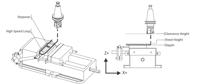
For machining walls, be sure to extend the cutting depth of full walls a little below the bottom wall without cutting into the machine table or vise jaws. This way, when you are removing stock from the back side of the part, there is no need to try to align another contour with the previously machined features, which can be difficult and inaccurate. Also consider taking a full depth finish pass on tall walls. This will ensure the walls are straight and not tapered.
It’s always a good practice to leave a consistent stock allowance when roughing the walls of your part. This will ensure the finish pass removes a consistent amount of material, help produce an even cutting pressure on the tool, and improve part accuracy.
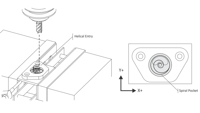
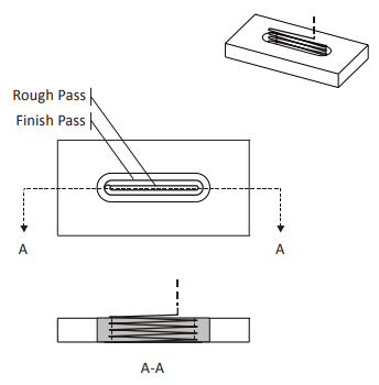
Pocketing can be used to remove excess material from any shaped pocket, such as from the spiral pocket below.
When doing rough pocketing passes, we recommend leaving a constant thickness on the walls and floor of the pocket. These can then be evenly removed by a finishing process.
Special roughing end mills with serrations to break up chips are one of the best tool types for removing material. However, they do produce a poor finish when compared to standard end mills. A final finish pass with a standard or finishing end mill will improve the surface finish.
If space allows it, use a helical motion when plunging into a pocket. If this isn’t possible you can use a Center-cutting End Mill, or drill a pilot hole and use that as an entry point to plunge into. Be sure to check with your tool manufacturer for the best feeds and speeds for plunge milling.
Lastly, when planning your toolpath, start near the center of the pocket and exit in a counter-clockwise direction. The tool will use climb milling while machining the pocket, which offers better cut conditions on rigid CNC machines.
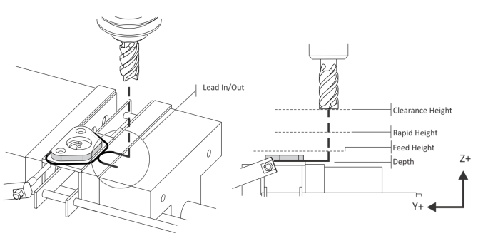
Slots can be machined with a variety of methods including contouring, pocketing, or specialized slot milling operations. We recommend always using a tool smaller than the width of the slot to maximize material removal and ensure adequate chip evacuation. When planning your toolpath, a ramp plunging move will provide the best results.
Bore toolpaths use a spiral motion to cut circular features like holes greater than 0.75in in diameter or circular bosses. The slow stepdown of the toolpath keeps the tool constantly engaged while not overloaded and results in an even surface finish.
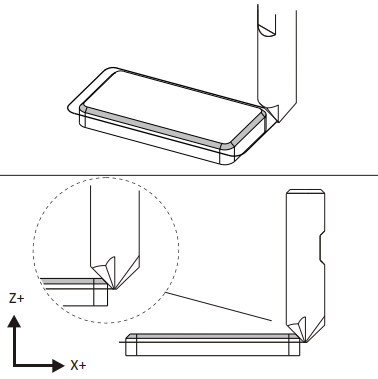
Chamfer milling is great for finishing 2D features. One of the most common workplace injuries in job shops is cuts on hands while removing parts from the machine. Breaking sharp edges with a chamfer helps keep hands cut free and operators safe and productive.
Here is a recommended formula for setting the depth of cut:
(tool_radius – tool_tip_radius) – chamfer_width – clearance
This formula will keep the cut off the tip of the tool, which gives better cut conditions leading to longer tool life and better surface finish. The clearance value will keep the cut from going past the outer diameter of the tool. Make sure your tool radius is large enough to leave some space on either side of the cut, so you aren’t cutting directly at the outer diameter or the tip diameter.
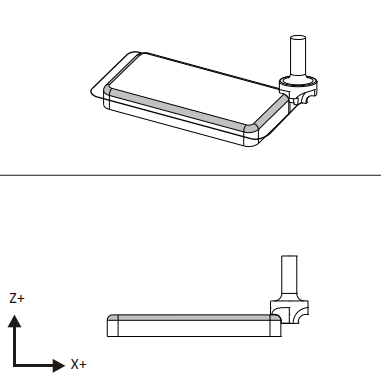
Radius milling uses a 2D Contour-like toolpath to produce an external fillet. Using the 2D toolpath requires a Radius Mill, but you can accomplish similar results with a Ball Mill and 3D contour toolpath.
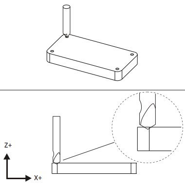
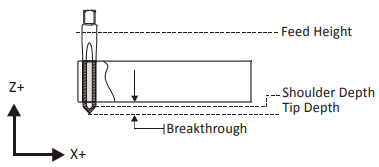
You can use center drilling to create a conical shape on the face of your part. Center drills are usually shorter and thicker than standard twist drills, so they create accurate cones that will help to keep later drills centered during their operation, and prevent them from “walking” or moving across the surface of the part. When planning a conical cut, we recommend spot drilling deep enough to match the diameter of the final drilled hole. If you want a chamfer on the final hole, spot drill a bit larger than the diameter of the drill.
Drilling will quickly create holes by removing material vertically. Drilled holes can be left as simple through holes, countersunk, counterbored, or tapped. A Peck Drill cycle can be used for deeper holes which will retract the tool slightly to break the chip, aiding chip evacuation and minimizing tool breakage.
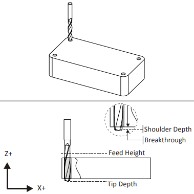
When configuring your CNC program be sure to know the desired end condition for each hole. If it is a through hole, drill deep enough to clear the drill tip as it plunges through stock. You’ll also want to include a breakthrough allowance to prevent flanging or burring.
Tapping created threads in previously drilled holes by coordinating feeds and speeds with thread lead. Your CAM setup will calculate feed rates based on cutting speed and threads per inch (TPI) of the tap. Be sure you have drilled the proper size hole for your tap. If the hole is too small, there is a risk of the tap breaking off inside the hole. If it is too large, the threads will not form properly.
Be sure to use adequate lubricant while tapping, whether your machine has automatic flood coolant or you manually brush the tip of the tap with oil before starting the operation. We also recommend tapping holes smaller than #6 by hand, as smaller taps break more easily. Both of these recommendations will help to avoid any unnecessary tool breakage.
When setting up your CNC program, remember to add a tapping tip depth that accounts for both the tip and initial taper of the tap, and be sure your hole is deep enough to accommodate the tap. Older CNC machines might also need a larger feed height so the spindle can reach full speed before plunging into material.
Knowing how to efficiently plan a 2D CNC machining project starts with understanding your toolpath types. A typical CNC job will start by facing material to the highest flat surface of a part. From there you can contour sides and start to work on additional features and fine details. Understanding the intricacies and limitations of each toolpath will give you the confidence needed to machine any part. You’ve taken a look at the fundamentals, now go practice the process!
Fusion 360 has all the CAM tools you need to easily set up your first CNC job. Try Fusion 360 for free today.
KEY WORDS FOR THIS PAGE :cnc machining Companies,cnc machining maker,cnc machining maker IN CHINA, cnc machining manufacturers,cnc machining manufacturing,cnc machining company near me,cnc machining suppliers,cnc machining suppliers in china, cnc machining service