中文

ENGLISH

 
News
Design Feedback & Modification Suggestion
Release time:2022-03-14

Just Tell Us Your Idea, Vowin Can Make It Come True.

From Scratch To 3D Model

Idea3D Model


Design Feedback & Modification Suggestion


5 Important Factors You Should Consider When Doing Injection Molding Design

This article will cover the most important considerations and provide some helpful tips for design engineers so they can avoid common pitfalls during design plastic parts process and production process.

Plastic injection molding is a process where molten plastic resin is injected into a heated steel mold cavity by injection molding machine that has been shaped to the desired part. Designers have to take many factors into consideration when designing product for this design process and manufacturing process.
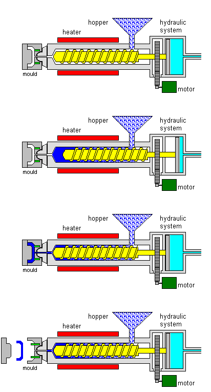
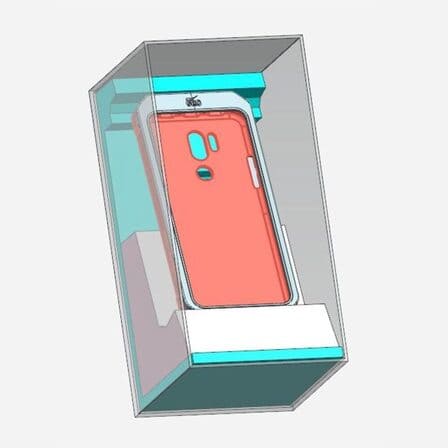
Injection Molding Process

Figure 1

Material Considerations

One of the main factors that will affect how a product is designed is the type of plastic material that will be used.

When designing injection molded parts, we need to consider the function of the plastic part, the environment in which it will be used and the design intent. This will help us determine material selection.

For example, if the product needs to be strong and withstand pressure, we would use a plastic material that is suitable for plastics injection molding process. If the product is going to be used in a wet or humid environment, we would use a plastics material that is resistant to moisture.

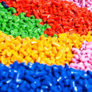
Injection Molding Raw Material

Figure 2

Different Plastic Materials Can Also Affect The Draft Angle Of The Product.

For example, if you are using a plastics material that is resistant to moisture, you will need to increase the draft angle to ensure that the plastic injection molding product comes out of the mold without being damaged.

Different Plastic Materials Are Suitable For Different Surface Treatments.

Some plastics injection molding products can do a high gloss finish, and some plastic injection molded parts are better suited for a sand-like surface texture. This is something we need to keep in mind when designing the product.

Different Plastic Materials Have Different Fluidities And Wall Thicknesses

This means that we need to consider which type of plastic material is going to be used as well as how it will affect the design of the plastic injection molding product. For example, if you are using a plastic material that has a low fluidity level, this would mean that it would be easier to design thinner walls for your part. If you are using a more rigid plastic, however, then you would need to design thicker walls for your product or else it might not come out of the mold properly.

Different Plastic Materials Are Designed With Different Ribs.

This is because not all plastics can be filled and some will show signs of shrinkage. If the product needs to be strong and withstand pressure, we would use a plastic material that is suitable for plastic injection molding and there should not be any signs of shrinkage.

Draft Angle

What Is A Draft Angle?

A Draft Angle is the angle that is used when creating a plastics injection molding product to help with extraction of the product from the mold.

Positioning of the injection angles is such that they run towards the direction of the mold’s pull and parting line.

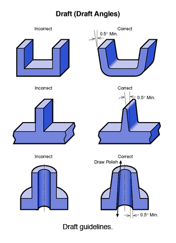
99% of your part design will require draft angle injection molding for a successfully made part and adding draft angle will not affect the tooling cost. The angle tapers on the molded part’s surfaces. Therefore, the part can easily slide across the mold’s cavities and cores as you’re demolding. 

Injection Molding Draft Angle

Figure 3

What Is The Reasonable Draft Angle Of Product?

An injection mold design needs to ensure the injection molding part comes out of the mold without damage or too much resistance during manufacturing process.

To avoid these issues, you need add the draft angle of the plastic part design from the parting line (drafting). Draft helps a part release from a mold with less drag on the part’s surface since the material shrinks onto the mold core. Limited draft requires an excessive amount of pressure on the ejection system that may damage parts and possibly the mold.

Generally speaking, there should not be any surface of the part that is exactly 90 degrees and sharp corners to the line of draw on the mold. It is difficult to design for this process because you have to design the shape of the part to ensure it doesn’t drag on the walls of the mold. A good rule of thumb is to design your product with 1 degree of draft per 1 inch of cavity depth. We would recommend a 3° degree draft angle whereas for a taller feature a draft angle should be up to 50° degree. 

What Are The Benefits Of Adding The Draft Angle?

To sum up, adding injection angles to your design features

  • Ensures smooth, uniform, unscratched finishes when required
  • Reduces the possibilities of damage to parts due to friction during ejection
  • Ensures the uniformity and integrity of other surface textures and finishes
  • Reduces wear and tear on the molded part
  • Reduces the chances of damaging the mold
  • Minimizes warping to your geometry
  • Reduces overall cooling time by eliminating or reducing the need for elaborate ejection setups
  • Offer both direct and indirect reduction to overall production cost

Texturing And Draft

If you are using a matte finish on your plastic parts, the draft angle will need to be increased in order to ensure that the product comes out of the mold without being damaged.

There Are Two Tips :

Injection Molding Product VDI Standard
Figure 4 VDI Standard
Finish SPI Standard Finishing Method Typical Surface Roughness Ra (Μm)
Super High Glossy finish A-1 Grade #3, 6000 Grit Diamond Buff 0.012 to 0.025
High Glossy finish A-2 Grade #6, 3000 Grit Diamond Buff 0.025 to 0.05
Normal Glossy finish A-3 Grade #15, 1200 Grit Diamond Buff 0.05 to 0.10
Fine Semi-glossy finish B-1 600 Grit Paper 0.05 to 0.10
Medium Semi-glossy finish B-2 400 Grit Paper 0.10 to 0.15
Normal Semi-glossy finish B-3 320 Grit Paper 0.28 to 0.32
Fine Matte finish C-1 600 Grit Stone 0.35 to 0.40
Medium Matte finish C-2 400 Grit Stone 0.45 to 0.55
Normal Matte finish C-3 320 Grit Stone 0.63 to 0.70
Satin Textured finish D-1 Dry Blast Glass Bead #11 0.80 to 1.00
Dull Textured finish D-2 Dry Blast #240 Oxide 1.00 to 2.80
Rough Textured finish D-3 Dry Blast #24 Oxide 3.20 to 18.0

Wall Thickness

A Good Rule Of Thumb

Commonly used materials such as ABS, external dimensions within 50mm, wall thickness 1-2mm; 50-150mm, wall thickness 2-2.5mm; 150-300 wall thickness 2.5-3mm.

Plastic injection molding wall thickness

Figure 5

Balance Between Strength And Weight

One of the most important aspects of plastic part design for plastic injection molding is controlling nominal wall thickness. If too thin wall injection molding, the part may be weak and not withstand the pressure of the plastic injection molding production process. If the walls are too thick, the molded part may be too heavy and not affordable and will have sink marks on the surface. It is important to find a good balance(uniform wall thickness) between strength and weight so that the part can be manufactured at an economical price.

Balance Between Cosmetic Appearance And Economical Price

Another consideration is cosmetic appearance. Thin wall injection molding can cause warping or other deformities in the finished product. Thicker walls will give a more solid appearance to the part. Having areas of the part cooling at different rates can cause warping issues. One way to avoid this is to make uniform wall thickness throughout the entire injection molded part.

The wall of your injection molded part is directly proportionate to both the total materials needed to make the part and the cooling time required.By changing the design to reduce the maximum thickness of the wall of your part, you will significantly reduce the cycle time and plastic injection molded part manufacturing costs.

Wall Thickness Recommendation For The Most Common Plastic Materials:
Material Recommended Wall Thickness [Mm] Recommended Wall Thickness [Inches]
ABS 1.2 – 3.5 mm 0.045” – 0.14”
Nylon (PA 6) 0.8 – 3.0 mm 0.03” – 0.12”
PC/ABS 1.2 – 3.5 mm 0.045” – 0.14”
PEEK 1.0 – 3.0 mm 0.04” – 0.12”
Polycarbonate (PC) 1.0 – 4.0 mm 0.04” – 0.16”
Polyethylene (PE) 0.8 – 3.0 mm 0.03” – 0.12”
Polypropylene (PP) 0.8 – 3.8 mm 0.03” – 0.15”
Polystyrene (PS) 1.0 – 4.0 mm 0.04” – 0.155”
POM (Delrin) 0.8 – 3.0 mm 0.03” – 0.12”

Ribbing

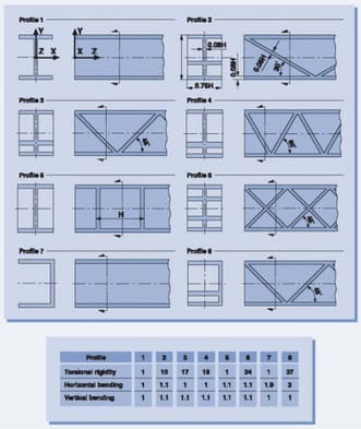
Ribbing is a common technique used to reinforce the strength of plastic parts. It is an effective way to add stability to thin walls and prevent warping. Ribbing also helps to distribute the load over a wider area, which reduces the amount of stress on any one point.

When Designing Ribs, You Need To Take Into Account The Following Factors:

The thickness of the ribs should be approximately 0.5 – 0.7 the thickness of the part wall. The spacing of the ribs should be between 2 and 3 times the rib thickness. The height of the ribs should be between 1/2 and 3/4 the part wall height.


Previous:Is Injection Molding Cheap?
Next: DFM Report, Mold Flow & Mold Design

Design

Prototype

Low Volume Production

Mold

Production

Contact